Environment: Quartus 18 Prime Standard Edition I use
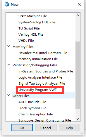
1. Create a new vmf file

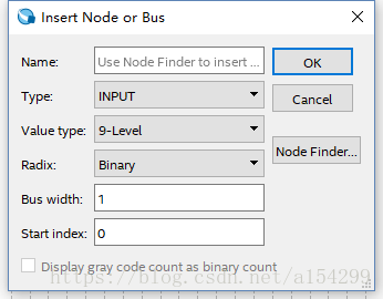
Add Node or Bus

2. Click Processing->Start->Start Test Bench Template Writer, then a .vht suffix file will be generated under the path of “project folder/simulation/modelsim” (the path may be different due to different personal settings).

3. Copy the .vht suffix file in the “project folder/simulation/modelsim” path to the “project folder/simulation/qsim” path.
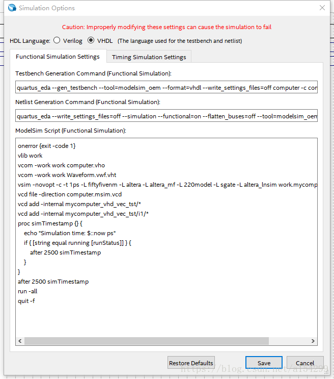
4. Open the vwf file created in step 1, click Simulation->Simulation Settings, the following interface will appear, modify the content in the Functional Simulation Settings tab as follows (note the direction of the path splitter in the Quartus software and the path under Windows The direction of the separator is opposite, one is “/” and the other is “\”):

(1) Change the path after “–vector_source” in the Testbench Generation Command (Functional simulation) column to the path where your own vwf file is located (note that the file name should also be modified to the name of your own file), “–testbench_file Change the path after “to the path where the .vht suffix file copied in step 3 is located (note that the file name should also be changed to the name of your own file);
(2) Change the path after “–output_directory” in the Netlist Generation Command (Functional Simulation) column to “project folder/simulation/qsim”.
(3) Modify the file name of vcom -work work Waveform.vwf.vht in the Modelsim Script (Functional simulation) column to your own file name.
(4) If you want to perform timing simulation, modify the content in the Timing Simulation Settings tab.
5. You’re done, just click Simulate after adding the input data.